BPMN Symbols Explained: A Practical Guide
A clear tutorial on BPMN symbols — what each shape means, how to use events, gateways and tasks, and how to connect nodes with sequence and message flows.

Why Learning the Symbols Pays Off
We model business processes nearly every week — claims flows, onboarding journeys, reconciliation cycles — and the single most useful thing a new team member can learn is not a tool. It is the BPMN symbols.
Here is the good news: the vocabulary is small and deliberately constrained. Business Process Model and Notation (BPMN) is a graphical standard maintained by the Object Management Group (OMG), and its 2.0 release is also ratified as an international standard, ISO/IEC 19510 (Source: Wikipedia). Learn roughly twenty symbols and a handful of connection rules, and you can read — and draw — almost any business process, no coding required (Source: UiPath Community Blog).
This is a practical tour of those symbols: what each shape means, how to use it, and — the part most guides rush — how the nodes actually connect to one another. We finish with a fully worked example you can read end to end.
The Four Building Blocks of Every BPMN Diagram
Before the individual shapes, the map. Every BPMN diagram is assembled from four categories of element (Source: UiPath Community Blog; IBM):
Category | What it does | Core shapes |
|---|---|---|
Flow objects | Define the behaviour of the process | Events (circles), Activities (rounded rectangles), Gateways (diamonds) |
Connecting objects | Link the flow objects together | Sequence flows, Message flows, Associations |
Swim lanes | Show who is responsible | Pools, Lanes |
Artefacts | Add supporting context | Data objects, Groups, Annotations |
Almost everything else is a variation on these. Let's take the three flow objects in turn, then the connectors that join them.
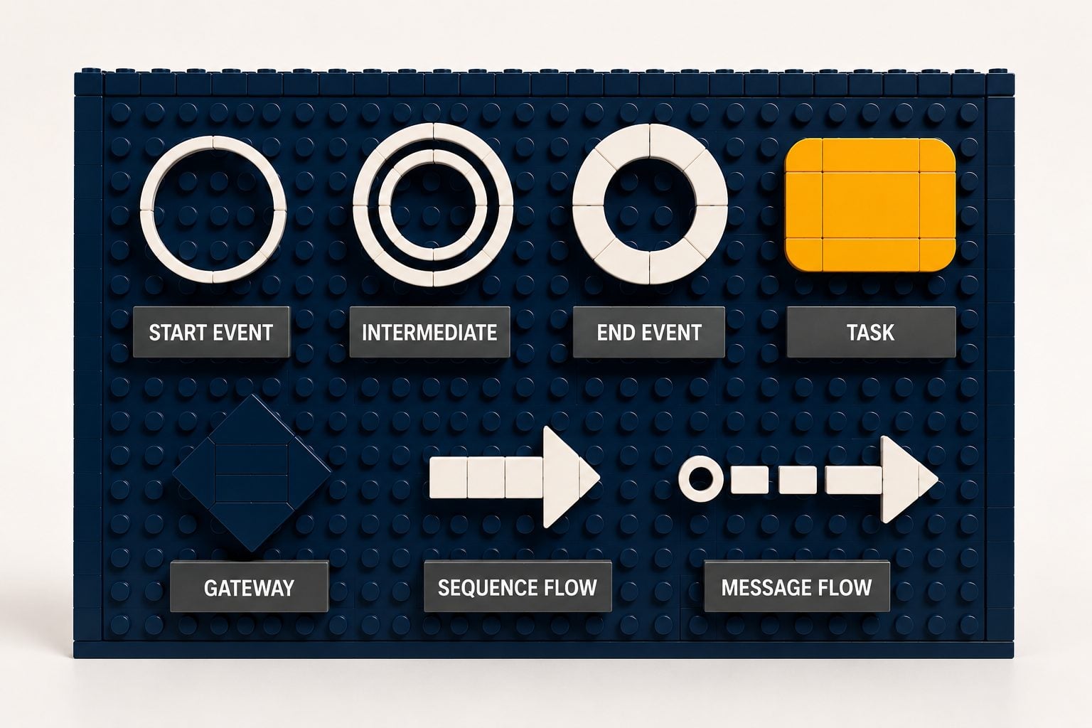
Flow Objects, Part 1: Events (the Circles)
An event is something that happens — as opposed to something that is done (Source: Wikipedia). Events are always circles, and the border style tells you when the event occurs, while the icon inside tells you what kind it is (Source: Gliffy).
Event | Symbol | Meaning | How to use it |
|---|---|---|---|
Start | Thin single-line circle | Triggers the process to begin | Every diagram needs at least one. Often a form or message kicks it off |
Intermediate | Double-line circle | Something that happens mid-process | Use to model a wait, a message received, or an error caught between steps |
End | Thick single-line circle | Marks a result / where a path stops | Every path should reach one. You can have several |
The icon inside the circle specialises it. A blank circle is "none"; an envelope is a message event; a clock is a timer; a lightning bolt is an error; a triangle is a signal (Source: Camunda). Events are also catching (they wait for a trigger, drawn with an open/outline icon) or throwing (they fire a trigger, drawn with a solid icon) (Source: IBM).
Rule of thumb: if your diagram has no start and no end event, you have a sketch, not a process. Always anchor both ends.
Flow Objects, Part 2: Activities (the Rounded Rectangles)
An activity is the work — a unit of something being done. The base shape is a rounded rectangle, and a small marker or type tells you how the work is performed (Source: InRule).
Activity | Symbol | Meaning | How to use it |
|---|---|---|---|
Task | Rounded rectangle | A single unit of work | The default building block of any flow |
User task | Rounded rectangle, person icon | Work a human performs | "Review application", "Approve payout" |
Service task | Rounded rectangle, gear icon | Work the system performs | An API call, a robot action, an automated step |
Script / Manual task | Rounded rectangle, script/hand icon | A script run, or non-system manual work | A transformation script; an off-system action |
Sub-process | Rounded rectangle with a + | A collapsed set of steps, hidden in one box | Tuck complex detail away; expand on a lower level |
Call activity | Rounded rectangle, thick border | A reusable process invoked from elsewhere | Define a process once, reuse it across diagrams |
That last one matters for clean models. A call activity lets one process invoke a predefined sub-process — which is how you avoid one sprawling diagram and build reusable blocks instead (Source: UiPath Community Blog).
Flow Objects, Part 3: Gateways (the Diamonds)
A gateway is a diamond, and it controls how the flow splits or merges (Source: Creately). The marker inside the diamond changes the logic entirely — this is the symbol people most often get wrong.
Gateway | Marker | Logic | When to use it |
|---|---|---|---|
Exclusive (XOR) | X (or blank diamond) | Either/or — exactly one path is taken | A yes/no or single-choice decision |
Parallel (AND) | + | All paths run at once | Steps that should happen simultaneously |
Inclusive (OR) | O | One or more paths, by condition | When several optional paths may each apply |
Event-based | Pentagon in a circle | The path whose event happens first wins | Wait for whichever of several messages/timers fires first |
There is a convention worth adopting from day one: put the question before the gateway, and label each outgoing path with its answer (Source: Camunda). "Is an update available?" sits in (or just before) the diamond; the outgoing arrows are labelled "Yes" and "No". A merging exclusive gateway later brings the paths back together.
Connecting Objects: How the Nodes Link Together
Flow objects are the puzzle pieces. Connecting objects are how the pieces join — and choosing the right connector is what separates a correct model from a misleading one (Source: gbtec).
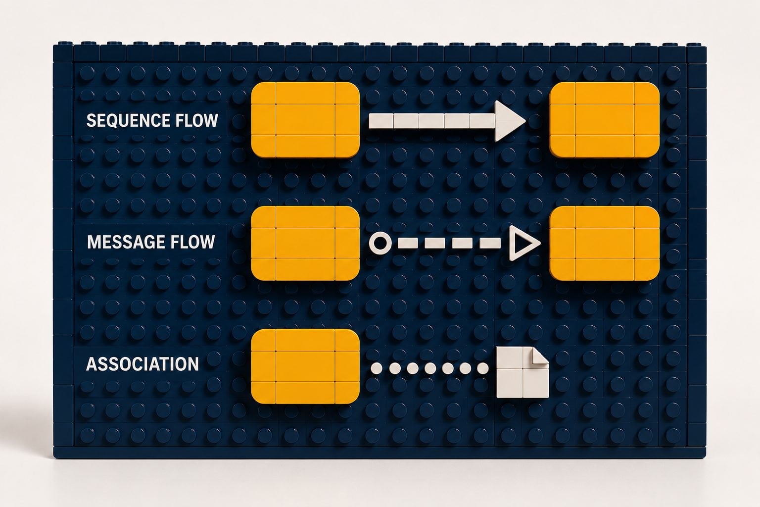
Connector | Appearance | What it connects | The rule |
|---|---|---|---|
Sequence flow | Solid line, solid arrowhead | Events, activities and gateways within one pool | Shows the chronological order of steps |
Message flow | Dashed line, open circle at source, open arrowhead | Across pools / participants | Shows information exchanged between participants |
Association | Dotted line, no arrowhead | An artefact to a flow object | Links data or a note to a step; does not affect flow |
This is the distinction to burn into memory: sequence flows stay inside a single pool; message flows cross between pools (Source: gbtec; IBM). If you find yourself drawing a solid sequence arrow from one organisation to another, you almost certainly want a dashed message flow instead.
Two refinements on the sequence flow are worth knowing. A default flow (a small slash near the source) is the path taken when no other condition is met. A conditional flow (a small diamond at the source) carries a condition directly on the line. Both let you express simple branching without always reaching for a separate gateway.
Swim Lanes: Showing Who Does What
Lay all of the above on top of swim lanes, and the diagram now answers who is accountable (Source: IBM).
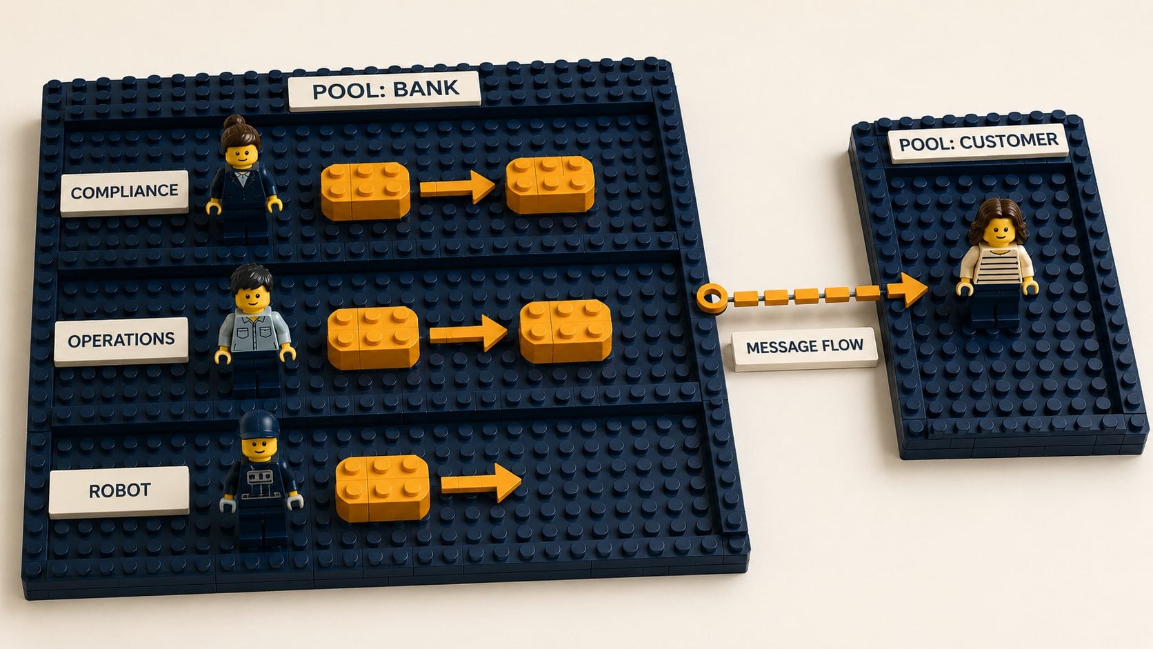
A pool is the biggest container — a participant, organisation, or system (a bank, a customer, a third-party provider).
A lane sits inside a pool and represents a role or function (the compliance team, the operations desk, an automated robot).
People routinely mix the two up. The simplest way to keep them straight: pools are the outermost boundary; lanes are the detailed rows within a pool (Source: Gliffy). And it ties back to the connector rule above — steps inside the same pool are joined by sequence flows, while two different pools talk to each other only through message flows.
Artefacts: Adding Context
Artefacts add information without changing how the process runs (Source: Creately).
Artefact | Symbol | Purpose |
|---|---|---|
Data object | Dog-eared page | Shows data an activity needs or produces (input/output) |
Group | Dash-dot rounded box | Visually clusters related steps; no effect on flow |
Annotation | Bracketed text | A plain-language note attached to part of the diagram |
Use them sparingly — they clarify, but a diagram crowded with notes is harder to read, not easier.
Putting It Together: A Worked Example
Now read a real one. This is a single-lane process in which someone updates the software on a company laptop — drawn entirely from the symbols above (Source: UiPath Community Blog).
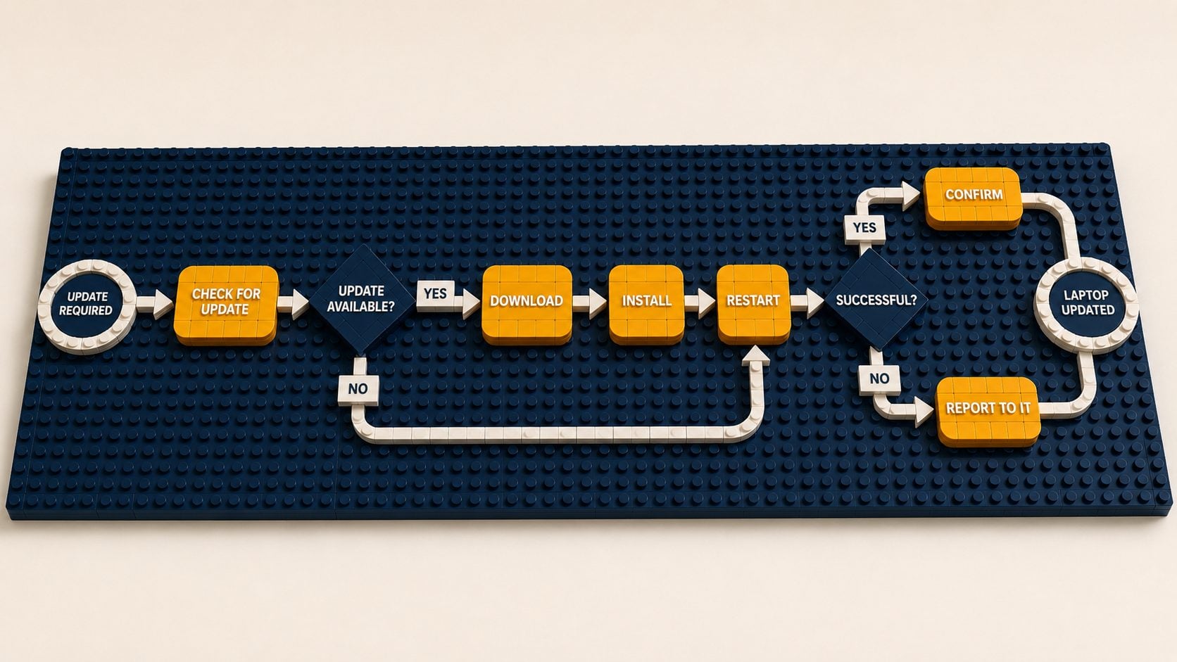
A start event (thin circle) fires: "software update required."
A user task (rounded rectangle): "check for software update."
An exclusive gateway (diamond): "is an update available?" — a sequence flow labelled Yes proceeds; No routes to notify IT and wait.
On the Yes path, three user tasks run in order, joined by sequence flows: download update → install update → restart laptop.
A second exclusive gateway: "is the update successful?" — Yes continues to confirm; No routes to report the issue.
A user task: "confirm update completion" on success, or "report issue to IT" on failure.
An end event (thick circle): "laptop updated" — every path resolves here.
Notice what the notation forced you to do: model the failure branches, not just the happy path. That is the discipline a flowchart lets you skip — and the reason BPMN, with its events, gateways and lanes, captures real processes more faithfully than a flowchart does (Source: UiPath Community Blog).
Rules and Conventions Worth Memorising
A short checklist that prevents most beginner mistakes:
Always start and end. Open with at least one start event; make sure every path reaches an end event (Source: gbtec).
Sequence inside, message across. Sequence flows stay within a pool; message flows cross between pools. Never join two pools with a sequence flow.
Question before the gateway, answers on the paths. Label every outgoing branch.
Pick the right diamond. XOR for either/or, parallel for "all at once", inclusive for "one or more".
Model the unhappy path. Exceptions are where production behaviour actually lives.
Hide complexity in sub-processes. Use call activities and sub-processes to keep each diagram legible.
Keep decision logic separate. For anything rule-heavy, pair BPMN with DMN (Decision Model and Notation) so business rules live in decision tables rather than buried in the flow (Source: UiPath Community Blog).
How We Use BPMN at Symprio

Symprio is a product engineering practice, not a slideware consultancy — we build and ship the systems we describe. For us, a BPMN diagram is not documentation produced after the fact; it is the contract we build against, agreed with a client's operations and compliance teams before any automation is written.
Two principles guide that. First, model before you automate — lanes, gateways, and exception paths get drawn and agreed first, so scope and ownership are legible up front. Second, make the model executable. BPMN 2.0 carries execution semantics, which means a correctly modelled process is not just a picture — it can be run. Models are saved as .bpmn XML, are versionable, and can be imported into an orchestration engine such as UiPath Maestro to coordinate robots, AI agents, and people against the exact flow you drew (Source: UiPath Community Blog).
For our regulated clients in Malaysian BFSI, that has a second payoff: a well-modelled process — named lanes, explicit approval gates, separated decision logic — doubles as the governance artefact that satisfies clear-ownership and audit expectations. (See our companion piece: why your BPMN diagram is the control plane for agentic automation →.)
Frequently Asked Questions
What are the four basic BPMN symbols?
The four core flow-object symbols are the event (a circle, something that happens), the activity or task (a rounded rectangle, work being done), the gateway (a diamond, a branching or decision point), and the sequence flow (a solid arrow that connects them in order). With these four you can read most simple diagrams.
What is the difference between sequence flow and message flow?
A sequence flow is a solid arrow that shows the order of steps within a single pool (one participant or organisation). A message flow is a dashed arrow that shows information passing between different pools — for example, between a bank and a customer. Sequence flows never cross pools; message flows always do.
What does a diamond mean in BPMN?
A diamond is a gateway — a point where the process path splits or merges. The marker inside sets the logic: an X (exclusive) means exactly one path is taken, a + (parallel) means all paths run together, and an O (inclusive) means one or more paths may run depending on conditions.
What is the difference between a thin and a thick circle?
The border tells you when the event happens. A thin single-line circle is a start event (the process begins). A double-line circle is an intermediate event (something mid-process). A thick single-line circle is an end event (a path concludes).
How is BPMN different from a flowchart?
A flowchart is an informal sketch of a happy path. BPMN follows the OMG global standard and forces explicit modelling of events, typed gateways, exception paths, connecting objects, and participant ownership via swim lanes — capturing real process behaviour, including failures, far more precisely than a flowchart.
What file format does BPMN use?
BPMN 2.0 diagrams are stored as .bpmn files in XML format. Because they are XML, models are versionable, comparable, and — crucially — executable by a compatible process or orchestration engine, rather than being a static image.
Start Modelling — and Make It Real
Knowing the symbols is step one. Turning a clean diagram into a governed, running process — orchestrating robots, agents, and people against it — is where the value lands, especially in a regulated environment.
That is the work Symprio does: model-first automation, built on a control plane your own team can own — sized to your reality, not a vendor brochure.
👉 Explore our process automation & orchestration services → 👉 Book a 30-minute discovery call → — no slide deck, just whiteboard thinking 👉 Read related: your BPMN diagram is the control plane for agentic automation →
Sources & Further Reading
UiPath Community Blog — Process modeling essentials (Anvita Dekhane): https://www.uipath.com/community-blog/tutorials/process-modelling-essentials
Object Management Group — BPMN 2.0 Specification: http://www.omg.org/spec/BPMN/2.0/
Wikipedia — Business Process Model and Notation (history, ISO 19510): https://en.wikipedia.org/wiki/Business_Process_Model_and_Notation
IBM — What is Business Process Modeling and Notation (BPMN)?: https://www.ibm.com/think/topics/bpmn
Camunda — BPMN 2.0 Symbols: a complete guide with examples: https://camunda.com/bpmn/reference/
Creately — The Complete List of BPMN Symbols and Their Meanings: https://creately.com/guides/bpmn-symbols/
gbtec — BPMN 2.0 modelling, rules and symbols simply explained: https://www.gbtec.com/wiki/process-management/bpmn/
Gliffy — Guide to BPMN Symbols: How to Read BPMN Diagrams: https://www.gliffy.com/blog/guide-to-bpmn-symbols
InRule — Common BPMN 2.0 Symbols: https://support.inrule.com/hc/en-us/articles/12660774454413-Common-BPMN-2-0-Symbols
#Symprio #EnterpriseAI #BPMN #UiPath #ProcessAutomation #BFSI #Malaysia
Symprio builds AI-enabled products for Malaysia's regulated enterprises — model-first, governed, and built to ship. symprio.com